Category Archives: Linux stuff

YOLOv8

I have been playing with Yolov8 for about 3 weeks now, I have been curating a British number plate tracking dataset. Using videos from youtube I trained a basic model and used this to help me label subsequent datasets. This takes the pain out of labeling every image manually. I have been using labelImg, anylabeling, and python scripts to extract the annotation section and view plates and perfect the dataset. This is the result so far which I am surprised how accurate it is. I have had to use a small batch size of 3 because I am training on 4k resolution images using a rtx3090.

as you can see above it still makes errors however, this was when I turned the confidence down to 0.02 to allow for more training data labels to be created, I then manually delete the false positives predictions by hand, which are not to numerous. This is easier than during the box labels.

Ford car 6000cd radio hack

Have you ever wanted to just plug your phone / audio device straight into a car radio. Here are the details to connect a 2.5mm audio jack or Bluetooth receiver into a standard car radio. The car is a Ford focus 2003 the radio model is a 6000cd. The pictures below show the solder points. there are 4 points that represent each speaker. So if you had a quadraphonic input source you could have it control each speaker individually. However, I am using a stereo Bluetooth output device so I paired red and white and black and red (thicker) together.

There are 4 connectors solder point inside the radio that will amplify a standard line signal.

XOR More than just a logic gate

I discovered an interesting thing about xor today. It can be used to encrypt data. Depending on how its used, it can be part of the strongest theoretically unbreakable encryption or the weakest.

The first example, where it is the strongest, is when it is used in a “one time pad”. A one time pad is a mechanism for encrypting data. Specifically where the Key data is the same size as the data that you want to send. This is often called the “plain text”. So the three ingredients are the

  1. “exclusive or”
  2. Random data.
  3. The useful data one wants to send.

To represent 2 and 3 I have two images.

Key

The image above is the Key.png this is our random data.

Hello

The file above is our data we want to encrypt and send.


XORHelloKey          convert Hello.png Key.png -fx “((255-u)&v)|(u&(255-v))” XORHelloKey.png

The image above is the encrypted version of our data. This was generated by xor’ing the message with our random data. It looks random, I hear you say, and you’d be correct. In fact very correct. You are looking at the “holy grail” of encryption. This is the starting point of where all encryption begins. This is the unbreakable cipher. This is because we have used 100% random data to encrypt it. Ok, so why don’t all systems use this and why does computer code cracking even exist. Well, there is one “huge” downside to this method. You would have to exchange the Key secretly with someone you wanted to send the message to. Needless to say this method is not used today to support https transfers.

World

Ok whats next? Suppose you could transfer tones of random key data secretly between you and a friend. You could communicate secretly with unbreakable encryption. You could until you run out of secret random data, that is, using this xor method. For if you were to recycle that data just once then all hell breaks lose. The image above is the second message I want to send and the image below is the encrypted xor’d version of it. Using the same key as above.

XORWorldKey        convert World.png Key.png -fx “((255-u)&v)|(u&(255-v))” XORWorldKey.png

Great looks random enough and it is. However, the fact that the same key has been used twice,  means that when they are xor’d together then the image below is produced.

XORORIG    convert XORHelloKey.png XORWorldKey.png -fx “((255-u)&v)|(u&(255-v))” XORORIG.png

And that is the result. It is like looking at a negative. However quite readable. If your on a Linux box you can easily, replay this for yourself using the commands and downloading the image files. Using image magic its possible to “xor” images on the command line. Enjoy.


Use one PWM signal channel to switch onboard FPV cameras and switch on and off recording.

This Arduino sketch will allow two buttons on an er9x radio control radio transmitter to be multiplexed into turning on and off any predefined state of pins on the Arduino. I used it to control recording, on and off, of the raspberry pi. This was allocated to one of the switches and the other to toggle around 4 cameras. This could be easily extended to more cameras though. The pins that are used can be wired up to a solid state analogue switch. such as,

MC74LVXT4066DTRG ANALOGUE SWITCH, QUAD, SPST, TSSOP-14

The code basically moves a walking bit from one pin to another enabling the CVBS signal from one camera signal at a time, to switch on and send the analogue CVBS signal to the onboard TV signal transmitter. This will then send the signal back to your receiver on the ground, where you can see a TV signal.

unsigned long duration;

int pin=A0;//This pin receives the signal from the receiver which is a 5v PWM signal
int ledPin = 13;//led to indicate recording.
int rec=0;//recored pin enable / disable

/*
Zones
The three ranges below create four zones. That is given the PWM signal can exceed the LOW_RANGE and HIGH_RANGE. These have been defined as constants as all radios and calibrations are different and you will need to tune yours. I have found the pulse width is stable enough to stay within these reliably with space for more in future. I have two switches on the radio transmitter. One is a toggle switch and one is a binary 2 state switch. I use the toggle switch to switch from camera to camera and the other to switch record on and off. When recording is enabled the width of the signal stays within zone 2 and 3 and when it is disabled zone 1 and 4. Then if there is a zone transition between 1 and 2 in record mode this will toggle the camera to the next and so on.
*/
//zone 1
const int LOW_RANGE   =1350;
//zone 2
const int MIDDLE_RANGE=1850;
//zone 3
const int HIGH_RANGE  =2350;
//zone 4

int chanTog=1;
void togChan() {//permits 4 states 0,1,2,3 then loops back to 0
if (chanTog > 1){
chanTog = 0;
} else {
chanTog=chanTog+1;
}

}

void setup()
{
Serial.begin(9600);
pinMode(ledPin,OUTPUT);//recording light only
pinMode(12,OUTPUT);//recording actual
//digital D7 needs to be low for ground.
//digitalWrite(7,LOW);

//digitalWrite(5,LOW);
//digitalWrite(6,LOW);
pinMode(2,OUTPUT);
pinMode(3,OUTPUT);
pinMode(4,OUTPUT);
pinMode(5,OUTPUT);
pinMode(6,OUTPUT);
pinMode(7,OUTPUT);
pinMode(8,OUTPUT);
pinMode(9,OUTPUT);

}//close setup

void loop()
{
duration = pulseIn(pin, HIGH);

//Debugging serial
Serial.print(rec,DEC);
Serial.print("\t");
Serial.print(chanTog,DEC);
Serial.println("");

//Camera switcher
 if ( chanTog == 3) {//These high and low states can be set arbitrarily.
 digitalWrite(2,LOW);
 digitalWrite(3,LOW);
 digitalWrite(4,LOW);
 digitalWrite(5,LOW);
 digitalWrite(6,HIGH);
 digitalWrite(7,LOW);
 digitalWrite(8,LOW);
 digitalWrite(9,LOW);
 }
 if ( chanTog == 2) {
 digitalWrite(2,LOW);
 digitalWrite(3,LOW);
 digitalWrite(4,LOW);
 digitalWrite(5,HIGH);
 digitalWrite(6,LOW);
 digitalWrite(7,LOW);
 digitalWrite(8,LOW);
 digitalWrite(9,LOW);
 }
 if ( chanTog == 1) {
 digitalWrite(2,LOW);
 digitalWrite(3,HIGH);
 digitalWrite(4,LOW);
 digitalWrite(5,LOW);
 digitalWrite(6,LOW);
 digitalWrite(7,LOW);
 digitalWrite(8,LOW);
 digitalWrite(9,LOW);
 }
 if ( chanTog == 0) {
 digitalWrite(2,HIGH);
 digitalWrite(3,LOW);
 digitalWrite(4,LOW);
 digitalWrite(5,LOW);
 digitalWrite(6,LOW);
 digitalWrite(7,LOW);
 digitalWrite(8,LOW);
 digitalWrite(9,LOW);

 /*  digitalWrite(2,HIGH);
 digitalWrite(3,HIGH);
 digitalWrite(4,HIGH);
 digitalWrite(5,HIGH);
 digitalWrite(6,HIGH);
 digitalWrite(7,HIGH);
 digitalWrite(8,HIGH);
 digitalWrite(9,HIGH);*/

 }

 if (duration >  MIDDLE_RANGE) { //enable record
   if( duration > HIGH_RANGE ) { //channel change
   togChan();
   delay(300);//debouncing noise delay. ms
   }
  rec=0;
  digitalWrite(ledPin,LOW);
  digitalWrite(12,LOW);
 } else {

   if(duration > LOW_RANGE ) {
   togChan();
   delay(300);
   }
 rec=1;
 digitalWrite(ledPin,HIGH);
 digitalWrite(12,HIGH);
 }

} //close loop


Roland dg dxy-1300 firmware exploration

I have extracted the ROM images from the two 27C512 chips inside the DXY-1300. I then passed them though a disassembler. This produced the asm files respectively below.

RolandDG_R15209223_LH53140H_8949E is the more interesting because it contains z80 code that starts at 0100h.

The asm files have beep passed as all code. However they need to be separated into data and code. As there is HPGL data starting around E000h in the R15209223 file and likely numerous other sections. This HPGL is the test image that is drawn when the device is powered on holding down the enter key.

boot sequence log

The goal for me is to use my Z80 ICE debugger from Tauntek http://www.tauntek.com/Z80-In-Circuit-Emulator.htm to analyze the memory until its booted.

An objective is to change and find how the pen speed works. As I have a laser burner I want to mount on it.

0100h is the default place the z80 jumps to for execution and called the ORG. I also expect Ill be able to use the boot test image at location “000e0e0” to print out back engineering debug info.

RolandDG_R15179881_LH2357H9_8943B.asm

RolandDG_R15209223_LH53140H_8949E.asm

RolandDG_R15179881_LH2357H9_8943B.BIN

RolandDG_R15209223_LH53140H_8949E.BIN

I am waiting until I receive some new 27512 chips in the post as it appears the originals in the plotter are ROM or in some way not writable by my EEPROM programmer lt866cs.

here Is a simple analysis of the most used sub routine calls within the code. I believe it identifies the main execution loop.

Heating control rcr10/433-GB RDJ10RF siemens

At the bottom of this post is the Arduino sketch you can use with the IRremote.h library. This library is used to send infrared light used on remote controls for television and video recorders and such. Interestingly the Siemens radio heating control uses the same encoding for its radio signal.

The structure of the radio signal is thus.

There are two sets of pulses. The first of the left is 32 bits is Infrared Sony encoded information. This is explained further here. The 32 + 32 bit data is sent 4 times in a row. I guess for redundancy and reliability. I found also if its only sent once it does not work. So 64 bits x 4 pulses are necessary.

http://www.righto.com/2010/03/understanding-sony-ir-remote-codes-lirc.html

the library IRremote does have an API sendSONY but I found it does not work for my purposes here, because the frequency passed in the library did not fit my frequency. So I used the SendRaw() function. I also defined my own one bit and zero bit and repeated them according to the array.

I have noticed the first set of 32 bits is always the same and it related to the second set. Its related in a way that is quite interesting. Its the original 32 bits but inverted (not gated).

I have found its inverted except for 2 bits. Bits 9 and 32. This bit inversion defines whether the signal being sent is on or off. You can see this from my code below.

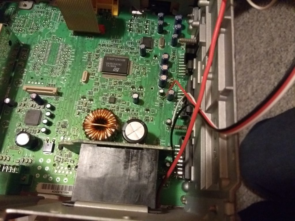
To get this code working on your own heater. You probably will need to change the bits that are sent here and there. As they are all unique for “security” sake. There are also dip switched to change the identity. You can record the signal from your timer with a 433 Mhz receiver via your sound card. Then interpret the ones and zeros for off and put it in the heating_code_second array. This stores the off signal. Then the array inverts the necessary bits to make the signal on. The whole command for the Arduino code accepts a 1 for on and 0 for off over the serial link.

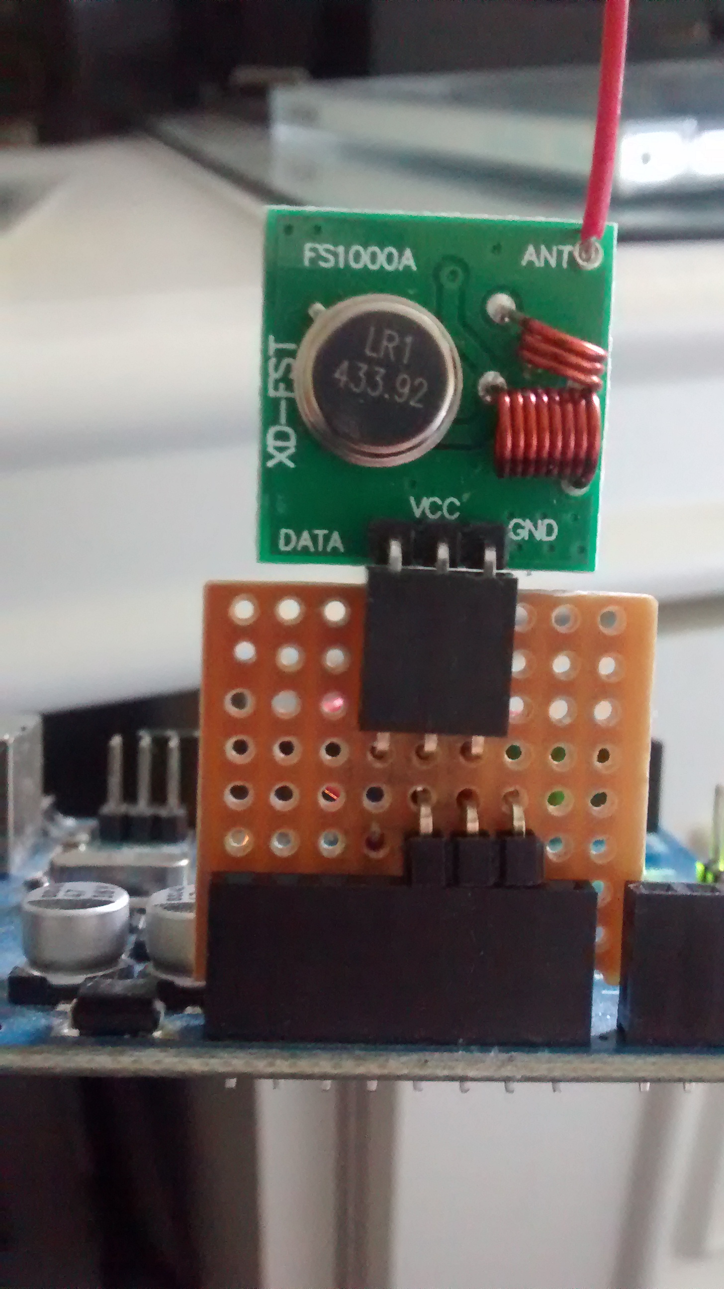
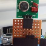
To interface the Arduino to the radio one needs a 433Mhz transmitter and  receiver pair. The receiver can be used to record the signal from the original siemens transmitter into audacity. Then run the sketch below to check it matches your out put.

IMG_20150218_142414073

/*
* IRremote: IRsendDemo - demonstrates sending IR codes with IRsend
* An IR LED/radio transmitter must be connected to Arduino PWM pin 3.
* Version 0.1 July, 2009
* Copyright 2009 Ken Shirriff
* http://arcfn.com
*/

#include <IRremote.h>

IRsend irsend;

// just added my own array for the raw signal
unsigned int digitalOne[4] = {0,820,370,0};
unsigned int radio_preamble_a[3] = {4800,820,0};
unsigned int radio_preamble_b[3] = {4800,0,0};
unsigned int digitalZero[4] = {0,200,370,0};
//off
unsigned int heating_code_first[33];
const unsigned int heating_code_second[33] =
{1,0,0,1,0,1,0,1,0,1,0,0,1,1,1,1,0,0,0,0,0,0,0,0,1,0,0,0,0,0,0,0,0};
String inputString = "";         // a string to hold incoming data
boolean stringComplete = false;  // whether the string is completevoid 
setup() {
Serial.begin(9600);
}

void loop() {// altered the code just to send/test my raw code
 if (stringComplete) {
 Serial.println(inputString);
 // clear the string:
 unsigned int input_num = inputString.toInt();
 inputString = "";
 stringComplete = false;
 unsigned int i=0;
 for (i=0;i < 33;i++) {
 heating_code_first[i] = heating_code_second[i];
 }
 if (input_num == 1) {//heating off
 //Serial.write("Heating on bit inversion");
 if (heating_code_first[32] == 0) {
 heating_code_first[32] =1;
 } else {
 heating_code_first[32] =0;
 } 
  if (heating_code_first[9] == 0) {
  heating_code_first[9] =1;
  } else {
  heating_code_first[9] =0;
  }
 }
 unsigned int pulse_count=0;
 for (pulse_count=0;pulse_count < 4;pulse_count++) {
  int bit_count =0;
  irsend.sendRaw(radio_preamble_b,3,40);
  for (bit_count=0;bit_count < 33;bit_count++) {
   if (heating_code_first[bit_count] == 1) {
   irsend.sendRaw(digitalOne,4,40);
   } else {
   irsend.sendRaw(digitalZero,4,40);
  }
 }

  delay(28);//Big delay between two pulses.
  irsend.sendRaw(radio_preamble_a,3,40);
  for (bit_count=0;bit_count < 33;bit_count++) {
   if (heating_code_first[bit_count] == 0) {
   irsend.sendRaw(digitalOne,4,40);
   } else {
   irsend.sendRaw(digitalZero,4,40);
   }
  }
 delay(15);
 }

 //Serial.println("Done");
 }

//delay(2000);
serialEvent();
}//close main loop

void serialEvent() {
 while (Serial.available()) {
 // get the new byte:
 char inChar = (char)Serial.read();
 // add it to the inputString:
 inputString += inChar;
 // if the incoming character is a newline, set a flag
 // so the main loop can do something about it:
   if (inChar == '\n') {
   stringComplete = true;
   }
  }
 }

Inkscape and 1980’s plotters

I had a Inkscape itch that needed scratching and as the holidays are upon us Christmas 2014. I found the time to write a patch for Inkscape.

Currently its not easy to use a plotter (DXY-1300) and have it switch pens in Inkscape. There is no method in the GUI to switch the pens. I read on news groups that it would be a good idea to have the stroke colours assigned to pen numbers. I have written this patch that allows pen stroke colour assignment to pen numbers.

screen shot

I used the stroke colour as this the colour the line changes. I also used the primary colours. Until somebody can modify the GUI this was a comprise.

inkscape_window

The export as hpgl now appears like so. With the pen assignments to pen numbers. Then the file will be produced with the necessary SP (Select pen) commands. The original Pen box has no function.

There are three files in the archive. They go in the extensions directory. I would also backup your originals first of course. Have fun and let me know if this helped.

These files are based on Inkscape 0.91pre3 However I don’t suspect these hpgl bit are in much flux so it should work for older versions. Mileage may vary.

hpgl_multipen.tar.gz

There a few things that could be improved upon in hpgl_encode. The order in which the pens are selected are based upon the order in which they are drawn in the editor. This is not ideal and to solve it is a “travelling salesman” type problem. This I believe has already been solved in the Inkcut plot extension. So it would be wise to integrate that code.

Here is a test file that will select each pen in order of 1 through to 8. The lines will be drawn from the bottom up. This can be used to test the new pen select code I have added.


An anomaly I noticed was that when selecting a pen the head returns to the same place. then continues drawing with the next command. This makes the pen change look inefficient as the head will return to where is once was, even if there is no line to be drawn. Then moves to the new position. Ideally before and after the Pen select command is executed the head would not return to the same location, but instead go to a new location. This seems to be a feature of the hardware and not something the command sequence automatically does.

It would be possible to have the head go to, a location nearest the next pen section then do a SP (Select Pen) so the head only travels back to this location and appears as if its travelling to a new location after pen selection. This would require eight locations outside the pen cartridges to be defined. This may be different for every plotter however. So unless somebody asks, I can’t see the justification in this one.

PipeLight

Pipelight


Today I was not feeling so well, man flue so I vegetating in bed on the net and stumbled across Netflix. I had a free month trial. I had heard that the Microsoft Silverlight is at the sites core and me being on Linux I would have an up hill battle. However, to my surprise it was easy to get this working. I followed the guide for my distribution (gentoo), there are guides for all other popular Linux flavours also for PipeLight

https://launchpad.net/pipelight

http://wiki.gentoo.org/wiki/Netflix/Pipelight

I think most people would ask why bother. I think its a matter of exploring what technologies are being used to deliver particular content. How its being used to maybe “control” users into certain decision that reflect buying decision.

And also to exercise my freedom and to show that large corporations will not encroach on my choice of operating system.

Don’t worry I know what your thinking (This guy uses a tinfoil hat to stop the government reading his thoughts). Not at all. You can either see what I’m getting at or don’t care 🙂 Let me know what you think and maybe give it a go yourself its easier than you think. The last and quite important reason I did it is to have the stability and security of Linux as the basis.


Bristol Synthesiser Emulations on Linux

Hi

Boy have I had some fun over Christmas. This years been interesting, in particular, because I have been listening to Portishead specifically, a track called Humming. At first, I thought it was a Theremin that was creating that spooky high pitched sound.  But after watching some videos on facetube I discovered it was a synthesiser. I know those things from the 80’s. I grew up in the 80’s unaware that there was this instrument revolution going on, that died by the late 90’s. These things to me, look like a piece of scientific equipment, I think that was the initial attraction, but with a keyboard stuck on.

I really wanted to see how it would be possible to make such a noise. These things, if you can find one for sale, are quite expensive and rare. Its basically an analogue computer with oscillators, square sawtooth, sinusoidal, etc, if you don’t know what those are then it does not matter anyway, most people just turned the knobs and see what sound came out.

So I was poking around with Google to see what was around in the opensource arena and I came across this. Bristol synthesiser I emerged it on my Gentoo box (windows versions are not available). After a few hours of playing I managed to get a sound that was alike to Portishead Humming with (-mini).
I took a screen shot so you can try it your self.
humming_portishead_mini_theramin

Have fun.